Track roller guidance system ELF
Track roller guidance system ELF
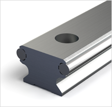
ELFS support rails are composite construction:
- An high-precision aluminum base element accommodates hardened and polished precision steel shafts that are used as tracks for track rollers.
- The special rolling-in process ensures the extremely robust bond of the steel shafts to the aluminum base element.
Accuracy of ELFS support rails
The parallelity values specified are determined using differential measurement. The straightness values of the finely aligned support rails are better than DIN EN 12020.
| Straightness | ||
| L [mm] | t1 [mm] | t2 [mm] |
| L < 1000 | 0,5 | 0,2 |
| 1000 ≤ L < 2000 | 1 | 0,3 |
| 2000 ≤ L < 3000 | 1,5 | 0,4 |
| 3000 ≤ L < 4000 | 2 | 2 |
| 4000 ≤ L < 5000 | 2,5 | 0,6 |
| 4000 ≤ L < 5000 | 3 | 0,7 |
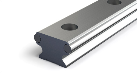
Fig. 1: Support rails ELFS
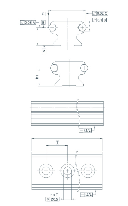
Fig. 2: Accuracy
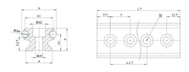
Hole pattern
If not otherwise stated, the support rails are supplied with a symmetrical hole pattern. An unsymmetrical hole pattern can also be provided upon request; in this case the minimum distances T1 and T2 must be observed.
All ELFS support rails are also available without holes: code OL.
Installation
- Lightly tighten screws
- Align support rails
- Tighten screws with tightening torque
For high loads, use washers that meet DIN 433 requirements. If installed with no side stop, comply with permissible side loads.
Special conditions for use
Under certain conditions of use, such as vibrations, alternating loads under high acceleration in combination with too soft connection structures, or incompletely supported support rails, the rolled-in steel shafts may drift by several millimeters in the aluminum base element. Where necessary, a positive self-locking axial support is recommended.
| Lenght of support rails | ||
| L [mm] | t3 | |
| Single part support rails | L < 1000 | ±2 mm |
| 1000 ≤ L < 2000 | ±3 mm | |
| 1000 ≤ L < 4000 | ±4 mm | |
| 4000 ≤ L | ±5 mm | |
| Several part support rails | Total length L | ±0,1 % |
| Tightening torque | |
| Screw | Tightening torque |
| ISO 4762-8.8 | MA |
| M5 | 5,8 Nm |
| M6 | 5,8 Nm |
| M8 | 24 Nm |
| M10 | 48 Nm |
| Max. lateral load | |
| Size | Lateral force |
| ELFS | Fz (zul) |
| 20 | 200 N |
| 25 | 330 N |
| 32 / 32E | 450 / 900 N |
| 52 / 52E / 52EE | 1000 / 1600 / 4000 N |
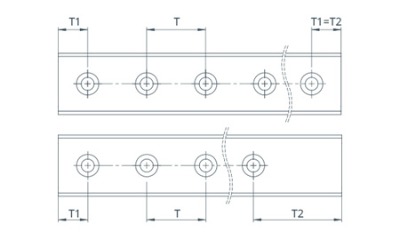
Fig. 3: Hole pattern
Support rails ELFS for track rollers
| Support rails ELFS for track rollers | Weight | ||||||||||||||
| Type | dw | b | A | h | b1 | h1 | h2 | d1 | d2 | M | L | T | TE | TEE | [kg/m] |
| ELFS20 | 4 | 20 | 17 | 12,2 | 16 | 9 | 7.6 | 4.5 | 8 | M4 | 3000 | 62,5 | - | - | 0,79 |
| ELFS25 | 6 | 25 | 21 | 15 | 19 | 10,6 | 8,5 | 5,5 | 10 | M5 | 3000 | 62,5 | - | - | 1,10 |
| ELFS32 | 6 | 32 | 24 | 20 | 26 | 15 | 12 | 6.5 | 12 | M6 | 6000 | 125 | - | - | 1,56 |
| ELFS32E | 6 | 32 | 24 | 20 | 26 | 15 | 12 | 6.5 | 12 | M6 | 6000 | - | 62,5 | - | 1,56 |
| ELFS32F | 6 | 32 | - | 10 | 26 | 5 | 3,5 | 6,5 | 12 | M6 | 6000 | 125 | - | - | 1,10 |
| ELFS52 | 10 | 52 | 40 | 34 | 42 | 25,1 | 21 | 11 | 19 | M10 | 6000 | 250 | - | - | 4,33 |
| ELFS52E | 10 | 52 | 40 | 34 | 42 | 25,1 | 21 | 11 | 19 | M10 | 6000 | - | 125 | - | 4,33 |
| ELFS52EE | 10 | 52 | 40 | 34 | 42 | 25,1 | 21 | 11 | 19 | M10 | 6000 | - | - | 62,5 | 4,33 |
| ELFS52F | 10 | 52 | - | 18 | 42 | 9 | 8 | 11 | 19 | M10 | 6000 | 250 | - | - | 3,05 |
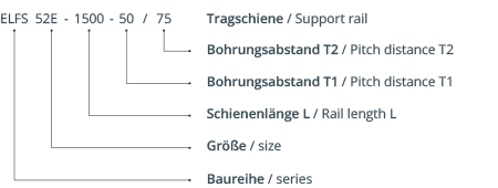
Ordering designation
- T1 and T2 depend on the rail length. In general: T1 (min) / T2 (min) = 20 mm. Other values are possible on request
- Maximum length of the single-part support rail; longer lengths are delivered in several parts
- Countersink depth for DIN912 screws - for use with DIN433 washers, DIN7984 screws should be used
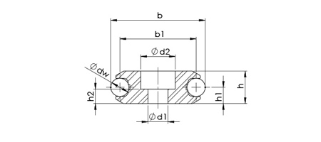
Fig. 4: ELFS .. F
Carriage ELFL for support rails
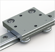
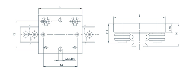
| Dimensions (mm) | Weight | |||||||||
| Type | Track roller | L | B | H | H1 | t4 | t5 | G4 | Hw | [kg/m] |
| ELFL20 | LFR50/5-4 KDD | 50 | 55 | 22 | 20,5 | 38 | 40 | M5 | 9 | 0,16 |
| ELFL25 | LFR50/5-6 KDD | 75 | 64 | 25 | 21,9 | 60 | 50 | M5 | 10,4 | 0,35 |
| ELFL32 | LFR50/8-6 KDD | 90 | 80 | 35,5 | 30 | 70 | 59 | M8 | 14 | 0,40 |
| ELFL52 | LFR5201-10 KDD | 100 | 120 | 54,3 | 43,2 | 70 | 90 | M10 | 19,5 | 1,00 |
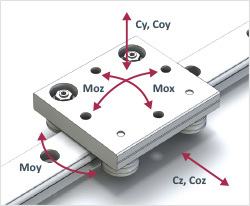
Fig. 5: Load directions and moments
| Load capacity | |||||||
| Load ratings [N] |
Moments [Nm] |
||||||
| Cy | Coy | Cz | Coz | Mox | Moy | Moz | |
| ELFL20 | 1330 | 845 | 2300 | 1620 | 7 | 22 | 11 |
| ELFL25 | 1330 | 845 | 2300 | 1620 | 8 | 41 | 17 |
| ELFL32 | 4210 | 2250 | 7100 | 4300 | 29 | 132 | 70 |
| ELFL52 | 10000 | 5120 | 17000 | 10000 | 108 | 300 | 148 |